Road Sensors
Road sensors like the one shown below were used around Area 51 in the 1980s and early 1990's to give base security an early warning of approaching vehicles. The sensors were hidden behind bushes near the dirt roads leading into the perimeter.
However, since they were sitting on public land, their use by the Groom Lake security forces without BLM approval was illegal. Also they were vulnerable to civilians tampering with them. It was just too much fun changing the ID code, which is set with the DIP switches shown below. Or to reverse the sensors, so that the indicated direction of travel was reversed. Needless to say that this caused quite some confusion among base security...
Most of the sensors have been removed, or rather replaced with more efficient and less obvious new sensors. There are only very few of the old sensors left on public land, and as far as we know all of them are inactive. The one below was sitting next to a dirt road on the northern slope of the Groom Range, less than ten miles from Rachel. It has "mysteriously" disappeared since the photos were taken.
Click on any of the photos for a larger high-resolution picture.
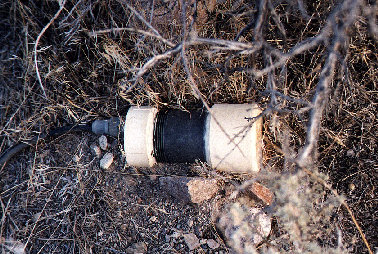
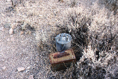
This small black and white cylinder is the actual sensor that detects approaching vehicles using magnetic induction. The right photo shows the transmitter in the round container with a short antenna, and the 12V-battery pack. Each transmitter has two sensors connected to it, positioned along the road about 10 ft. apart, so that the direction of a passing vehicle can be determined.
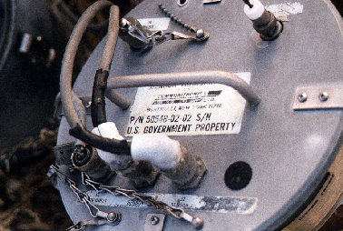
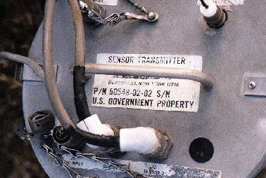
The top of the sensor transmitter unit. In the high-resolution version of these photos you can clearly read the manufacturer and even the serial number of this particular unit. The antenna is on the upper right, and the connectors at the bottom of the picture are 12V input, sensor 1 and sensor 2. Apparently the units were originally designed for three sensors, but the third input is not used.
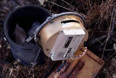
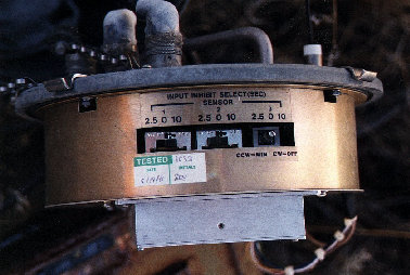
This is what the inside of the unit looks like. Most of the round container is empty, or rather filled with sandbags to keep the unit from falling over. The round golden unit contains the digital address logic (see below) and the sensor interface with a variable input inhibitor to adapt it to different types of sensors. Again, it can be seen that the unit was originally designed for three sensors. The actual transmitter is the silver box that is mounted at the bottom of the round unit.
Notice the sticker that says that the transmitter was tested on 6/19/1986. It is very likely that that is about the time when these sensors were put in service. Long before the public became aware of Area 51.
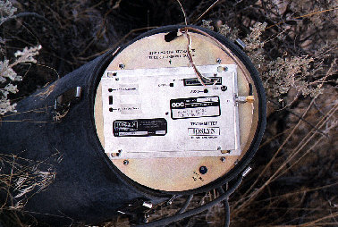
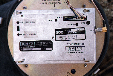
This is the actual RF transmitter unit. It can be set to operate on either 496.25 MHz or 497.75 MHz. Both frequencies can be adjusted independently. The connector J1 is the digital input, and the RF output goes to the antenna, which is mounted on top of the digital/interface unit. The antenna is about 30 cm (12 inches) long, which is 1/2 wavelength at that frequency.
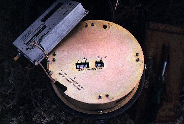
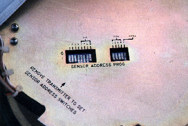
After removing the RF transmitter, the bottom of the digital/interface unit reveals an array of DIP switches, which allow giving each individual sensor transmitter its own address. The address is set in BCD code, and as you can see the address range goes from 0 to 1999. In other words, per frequency a total of 2000 transmitters can be used. This particular unit is set to address 1078.
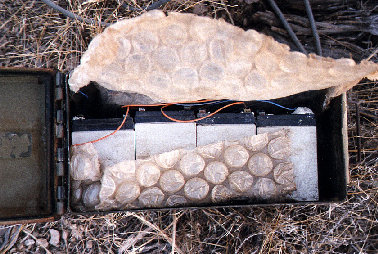
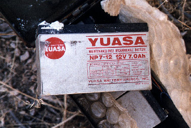
The battery pack contains four 12V/7Ah rechargeable batteries. They are wired parallel, which makes for a total of 12V/28Ah. Assuming that the unit uses 10 mA in standby mode, the battery pack would last for almost 4 months.
Since they are no longer serviced, the batteries in this particular unit are in a state of advanced decay, and pose a first class environmental hazard.
© Copyright 1999-, Dreamland Resort. All rights reserved. Copyright Policy Privacy Policy Page last modified 08/04/2018


